AutoCAD Plant 3D Validation Spec Sample
1 Introduction
Standards are an integral component in the creation of meaningful project documents across a variety of industries. Applications can take different approaches to ensure standard compliance, ranging from rigid enforcement to assisted notification. An example of the former would be an application that ships with a predefined set of industry layers, and does not allow the user to create or modify this default set. An example of the latter is the standards utility included with vanilla AutoCAD, which provides a system tray notification mechanism that alerts the user when the drawing is not standards compliant as well as a standards checking utility which reports detailed information on each standards violation.
Standards are an important part of P&ID documentation as well. The Cork application’s project management environment makes it easy for drafters to ensure standards compliance by enabling a Tool Palette work-flow that only exposes the discrete set of components appropriate for the current project context. Cork also strives to strike a balance, however, and has the flexibility to allow users to break standards by creating AutoCAD primitives or introducing external components that are not part of the core project. To address these cases, Cork includes a Validation feature that audits one or more drawings from the current project and reports on the following potential sources of error:
- Size or other property mismatches between in-line components and their associated lines
- Lines that don’t terminate
- Conflicts in flow direction
- Unmated off-page connectors
- Incomplete tags
- Non-annotated lines
- AutoCAD primitives (annotations, lines, etc.) and blocks
1.1 Terminology
| Term | Definition |
|---|---|
| Annotation | A general term for text-based AutoCAD primitives. Examples of annotations are text, dtext, mtext, and dimension objects. For the purposes of this document, AutoCAD-based annotations are distinctly different from native Cork |
| Attribute | An optional data element that can be associated with an AutoCAD block. For example, a block representing a valve might have associated attributes representing its type and size. Attributes can also expose an optional annotation element that is placed with individual block instances. |
| AutoCAD Primitive | Native AutoCAD objects such as lines, arcs, and circles. |
| Block | Compound objects built up from a collection of AutoCAD primitives. Blocks provide a convenient mechanism for users to aggregate individual elements into a group which can be inserted as a single unit, saving the user from having to manually redraw the individual elements that constitute it. |
| Component | Native Cork object types. Cork exposes a number of different object types, including the following:
|
| Standard |
An accepted convention that details best practices for a given industry in a particular region. For working with a P&ID, a standard might define components such as agreed upon symbols for representing different component types using blocks, as well as layering conventions, linetype conventions, etc. Applications take different approaches with regards to standards, ranging from rigid enforcement to complete drafting freedom. Cork strives for a middle ground, allowing users to draft as they are accustomed to while providing notification when non-standard or problematic situations arise and also supporting auditing for a complete accounting of all problem states across a given project. |
| Tag | An annotation element that displays property information about a Cork component. |
| Tool Palette | An AutoCAD UI element for grouping tools. In Cork, different projects populate the tool palette with varying tools. CAD Managers will typically define the available components, standard linetypes, etc. that are available for a given project when creating the project. This process populates the palette with appropriate set of project-based tools. |
2 Feature Design
2.1 Overview
Cork (AutoCAD Plant P&ID) supports a project-based work-flow. A CAD Manager will typically setup a project, identifying the appropriate components (lines, pumps, valves, tanks, etc.) that drafters will work with. Drafters will create individual P&IDs largely by dragging components from AutoCAD Tool Palettes and dropping them into a drawing. Throughout the drafting process, users can potentially introduce errors in a number of ways, most notably the following:
1. By placing an AutoCAD primitive or block into the drawing, rather than placing a Cork component via the project Tool Palette.
AutoCAD objects have no direct linkage to the Cork context, and thus will not show up in reports. This can be particularly problematic in cases where the AutoCAD object closely resembles a Cork object – for example, inserting an AutoCAD block into a drawing rather than a Cork recognized component. If a symbol with similar or identical appearance exists in the current project, consumers of hard-copy printouts of the P&ID will potentially interpret the AutoCAD block as the Cork component, but any reports generated for the project will not include the AutoCAD block.
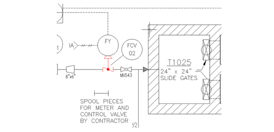
2. Property mismatches between in-line components and their associated schematic lines.
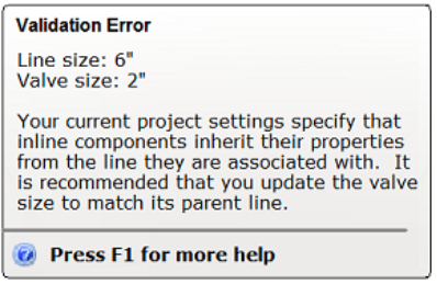
By default, in-line components inherit a number of properties from the line they are associated with. If users subsequently change a line property such as size, the in-line component updates itself to reflect the new size. This linkage is not bidirectional, however – if users update the size of the in-line component through the Properties Palette, a mismatch can occur between the component and the line.
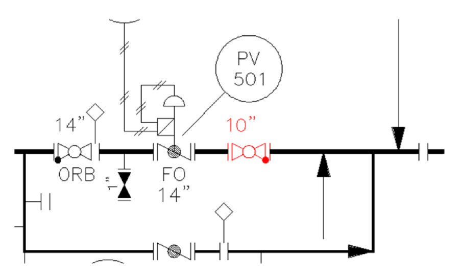
3. Schematic lines that don't terminate.
Cork project lines should terminate either through a connection to an end-line component or an end of line symbol with associated annotation indicating what the termination means (e.g., air vent, water outlet, drain, etc.). Users may inadvertently neglect to terminate one or more lines in a project drawing, and these by default are flagged as errors.
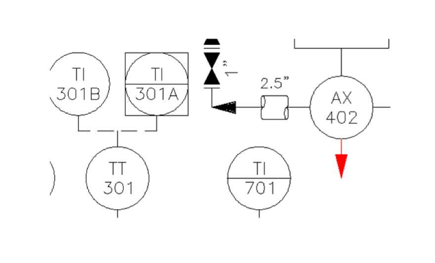
4. Process lines that aren't annotated.
All process lines in a P&ID should be assigned a tag and properly annotated in the P&ID. Any process line that isn’t should be flagged as a validation error.
5. Incomplete tag data.
Tags are composed of a number of fields. If any of the fields in a given tag are blank, a validation error is returned.
6. Off-page connectors that don't resolve.
Off -page arrows are used in P&ID drawings to indicate lines that are continued in another drawing file. It is typical to place off-page connectors initially without pointing them to another drawing file, largely because the drafter isn’t sure which file to use or because the other file might not yet exist. Once the project has been completed, however, it is important that all off-page connectors properly resolve.
7. In-line or end-line components that appear to be associated with a line but which aren't programatically connected.
When creating drawings, users can either fail to properly establish a connection between a component and a line when initially placing the component, or after initial placement by dragging the component away from the line.
8. Conflicts in flow direction.
All lines have a flow property (as do some in-line components such as valves), which indicates the direction of movement for the material conveyed by the line. Flow direction can optionally be depicted symbolically in P&ID drawings by an arrow, but oftentimes flow is not graphically depicted. In these cases, it may be difficult for users to identify flow conflicts without an auditing tool.

9. Duplicate tag numbers for a given object type.
In most cases it is desirable (if not required) to assign unique tag numbers to objects of a given type, such as pumps. Duplicate tag numbers can lead to confusion, and make it impossible to unambiguously identify a component.
When any of these situations occur in a project drawing, it is important that Cork notify users that problems exist and provide a mechanism for reviewing and fixing them. This is handled in the following ways:
- Automatic notification of problem states when users attempt to perform certain operations on a project drawing that has validation errors. When users perform these operations from within the project context, an alert is displayed which notifies users that the drawing has validation problems. Users can choose to ignore the alert and continue with the operation, or to review the problems in a secondary UI. By default, a validation operation will automatically be performed when users attempt to plot or publish a Cork project drawing.
- User-initiated validation operation. Users can also explicitly invoke a validation operation on one or more project drawings by creating a selection set in the Project Manager, then right-clicking and choosing the Validate option.
- Background polling of project drawings. Users will be able to configure AutoCAD so that validation checks are performed in the background at specified polling intervals. When configured for this mode of operation, a tray icon will be exposed at the bottom of the AutoCAD drawing editor. If any validation errors are encountered during a polling interval, a bubble notification will be displayed alerting users to the problem.
Default Workflow
The default, out-of the box configuration of the Cork Validation feature will enable background polling of project drawings for validation errors. When a Cork project is open in the AutoCAD drawing editor, a validation operation will run as a background process at a user-settable interval (initially set to every fifteen minutes). If any validation errors are encountered in any project drawings, an icon indicator is presented in the Project Manager tree to visually differentiate the problem drawings . A bubble notification is also displayed in the system tray to alert users to the problem.
The Project Manager will introduce a new Validation Errors panel, from which users can traverse a set of validation errors in individual drawings selected from the tree, or all errors in the project by selecting the project node. Each error will also be visually indicated in the drawing editor via a markup with an associated annotation describing the encountered error condition, as depicted in the following screenshot:
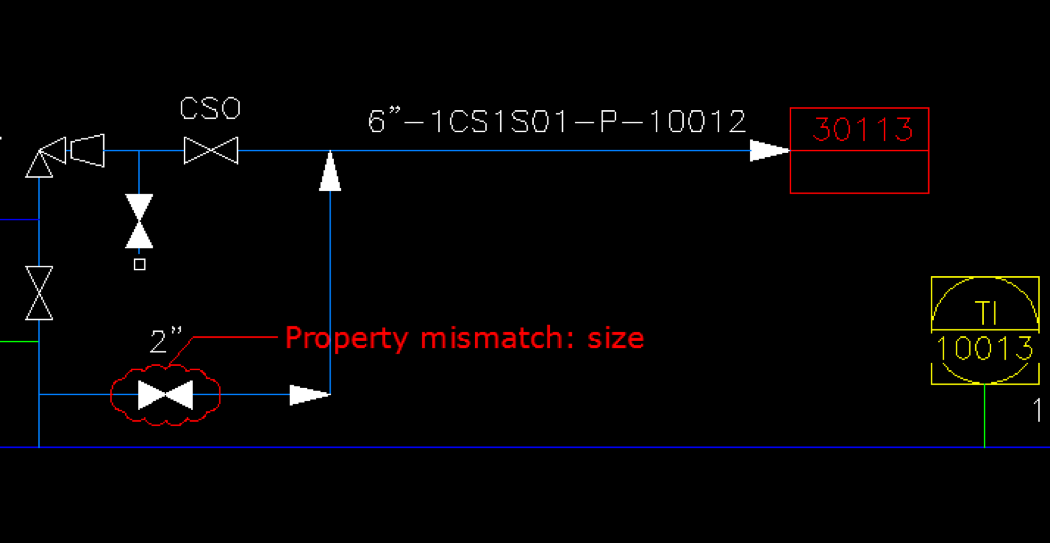
The markup element is currently envisioned as a pseudo object type. As opposed to true AutoCAD objects, the validation markup will not be directly user selectable. To be more specific, users will not be able to click on the validation markup to perform operations on it (for example, in order to move or delete it). When users mouse over the markup object, an enhanced tool-tip will be displayed, leveraging the Raptor UI enhancements being undertaken by the AutoCAD team. This tool-tip will provide additional information about the error.
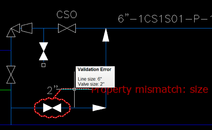
By leveraging the progressive disclosure element of the enhanced tool-tips, more detailed User Assistance Help content can also be provided for individual error types if the user continues to hover the cursor over the validation markup object.
